
Document original : NIDays 2016 : Test HIL et simulation temps réel d'électronique de puissance (PDF, 2,7 Mo, 34 pages)

Using Cutting-Edge Tools to Test Firmware
for Uninterruptible Power Supplies
HIL & Real time Power Electronics Simulation
Jean-Louis Schricke - MESULOG
SOCOMEC Activities
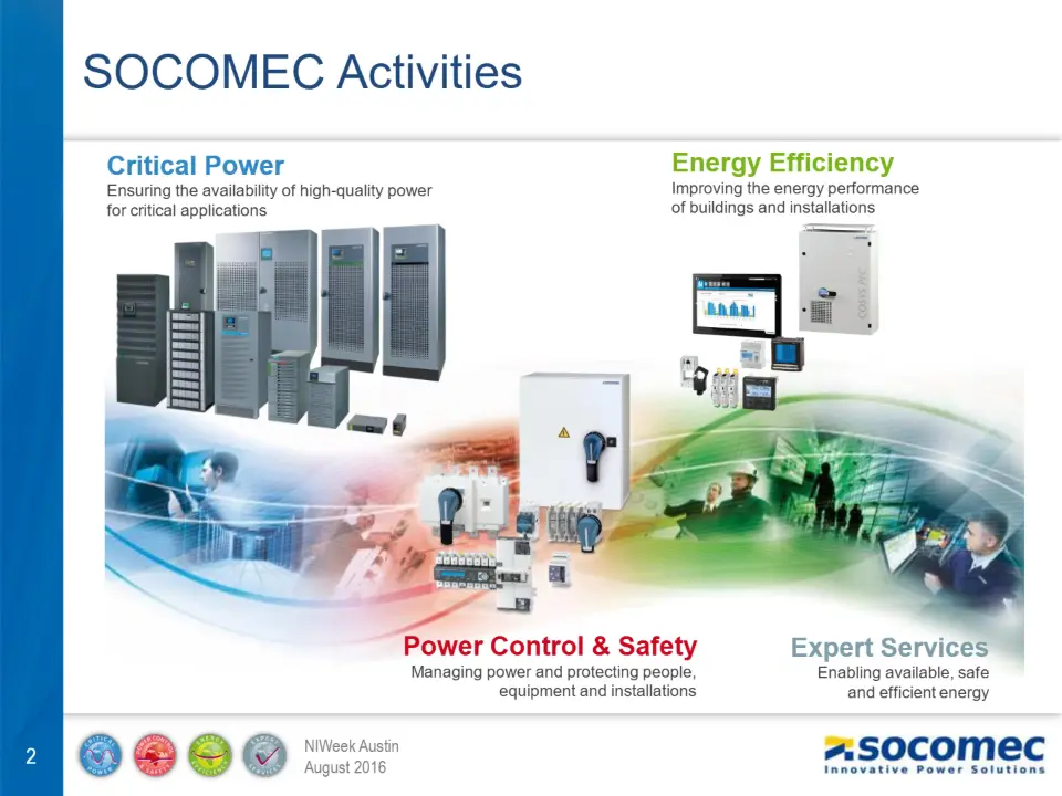
Energy Efficiency
Ensuring the availability of high-quality power for critical applications
Improving the energy performance of buildings and installations
Power Control & Safety
Expert Services
Managing power and protecting people,
Enabling available, safe
equipment and installations
and efficient energy
SOCOMEC Figures
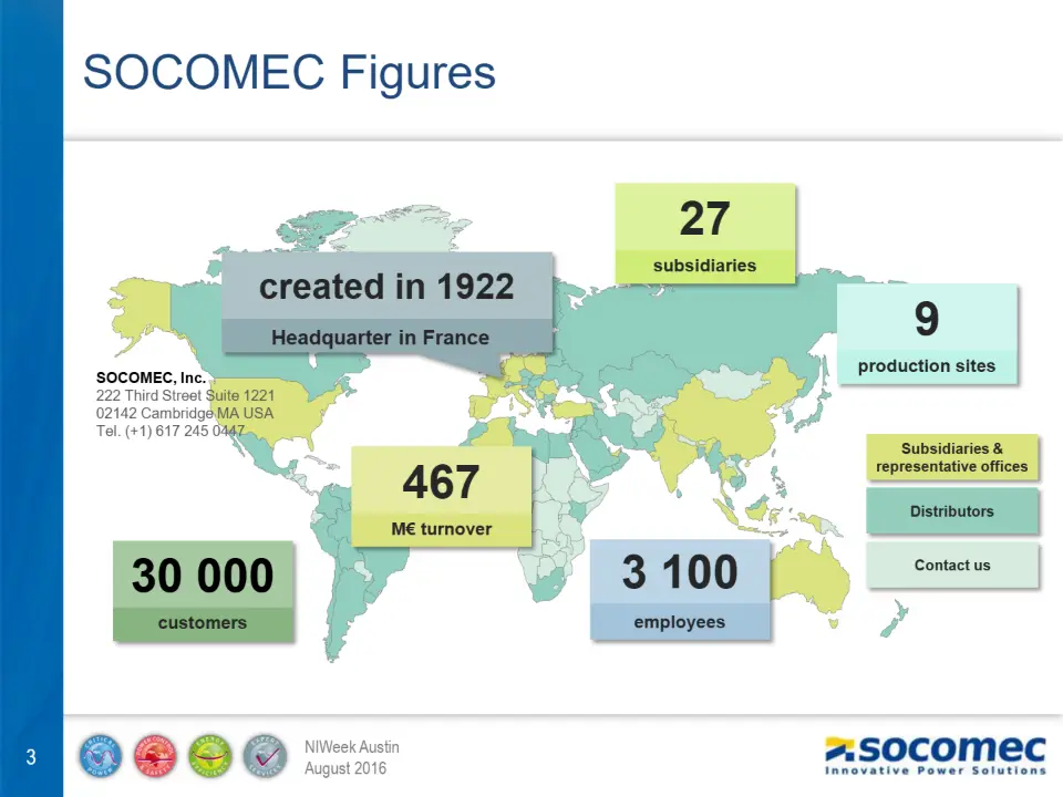
subsidiaries
created in 1922
Headquarter in France
SOCOMEC, Inc.
222 Third Street Suite 1221 02142 Cambridge MA USA Tel. (+1) 617 245 0447
production sites
Subsidiaries &
representative offices
Distributors
M€ turnover
Contact us
30 000
3 100
customers
employees
Specialist positioning
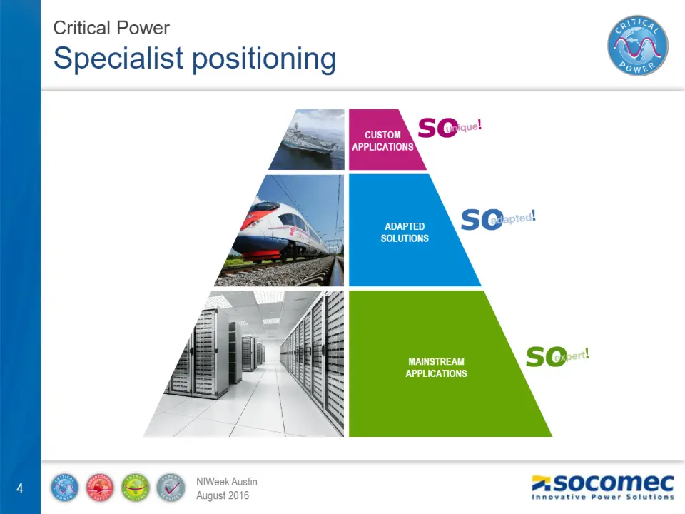
CUSTOM
APPLICATIONS
ADAPTED SOLUTIONS
MAINSTREAM APPLICATIONS
Customer confidence
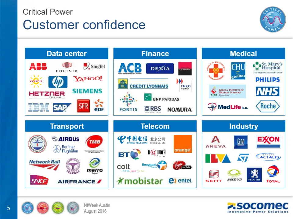
Data center
Finance
Medical
Transport Industry
Telecom
A wide range of solutions…
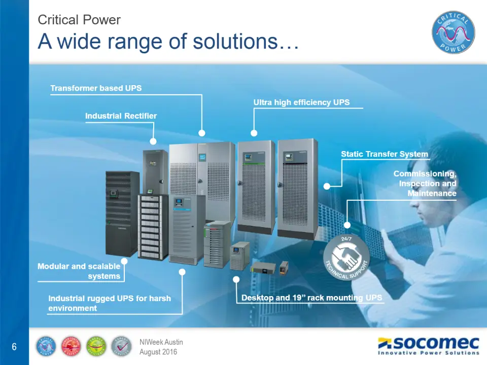
Transformer based UPS
Ultra high efficiency UPS
Industrial Rectifier
Static Transfer System
Commissioning, Inspection and
Maintenance
Modular and scalable
systems
Industrial rugged UPS for harsh environment
Desktop and 19’’ rack mounting UPS
Continuous innovation
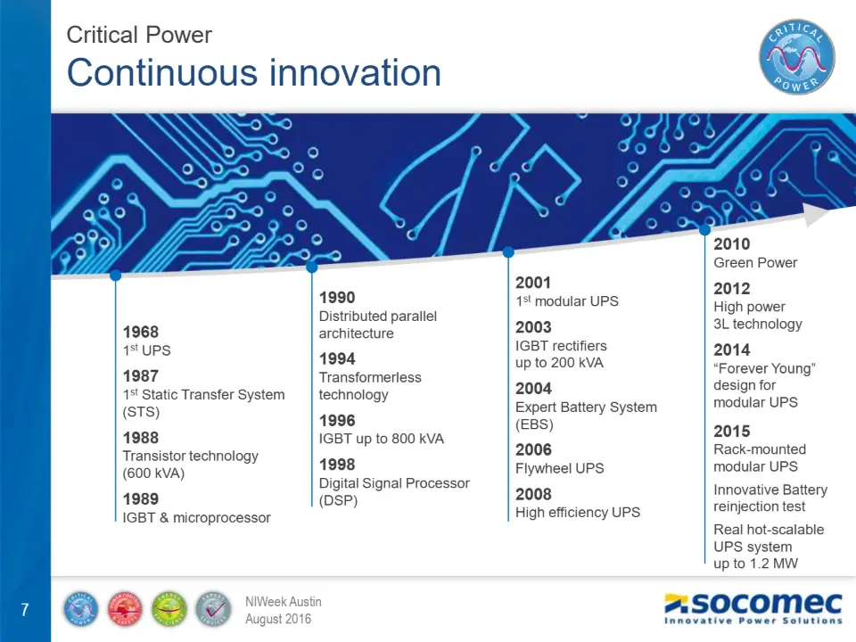
Green Power
1st modular UPS
High power 3L technology
Distributed parallel architecture
1st UPS
IGBT rectifiers up to 200 kVA
“Forever Young” design for modular UPS
Transformerless technology
1st Static Transfer System (STS)
Expert Battery System (EBS)
IGBT up to 800 kVA
Transistor technology (600 kVA)
Rack-mounted modular UPS Innovative Battery reinjection test Real hot-scalable UPS system up to 1.2 MW
Flywheel UPS
Digital Signal Processor (DSP)
IGBT & microprocessor
High efficiency UPS
2016: why an HIL simulator ? Continuous improvement
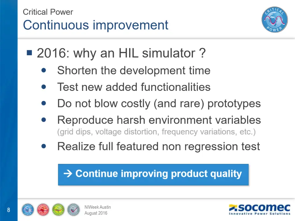
Shorten the development time Test new added functionalities Do not blow costly (and rare) prototypes Reproduce harsh environment variables
Realize full featured non regression test
(grid dips, voltage distortion, frequency variations, etc.)
Continue improving product quality
Continuous improvement
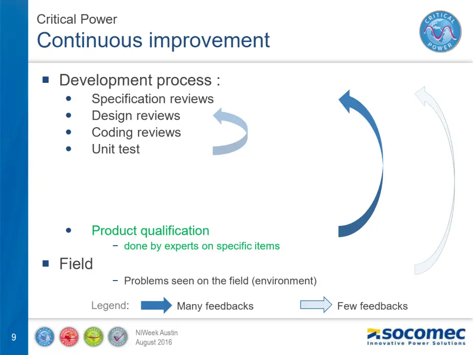
Development process :
Specification reviews Design reviews Coding reviews Unit test . . . . Product qualification
− done by experts on specific items
Field
− Problems seen on the field (environment)
Legend: Many feedbacks
Few feedbacks
Continuous improvement
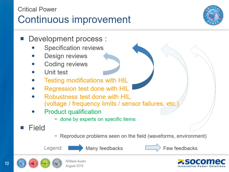
Development process :
Specification reviews Design reviews Coding reviews Unit test Testing modifications with HIL Regression test done with HIL Robustness test done with HIL
(voltage / frequency limits / sensor failures, etc.)
Product qualification
− done by experts on specific items
Field
− Reproduce problems seen on the field (waveforms, environment)
Legend: Many feedbacks
Few feedbacks
Continuous improvement
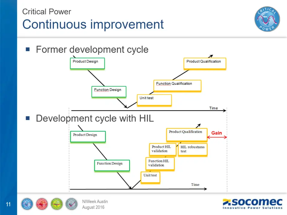
Former development cycle
Development cycle with HIL
Gain
HIL requirements
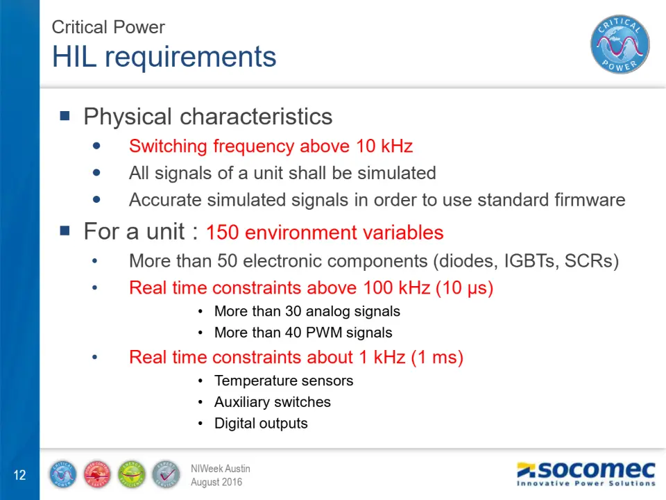
Physical characteristics
Switching frequency above 10 kHz All signals of a unit shall be simulated Accurate simulated signals in order to use standard firmware
For a unit : 150 environment variables
- More than 50 electronic components (diodes, IGBTs, SCRs)
- Real time constraints above 100 kHz (10 μs)
- More than 30 analog signals
- More than 40 PWM signals
- Real time constraints about 1 kHz (1 ms)
- Temperature sensors
- Auxiliary switches
- Digital outputs
HIL requirements
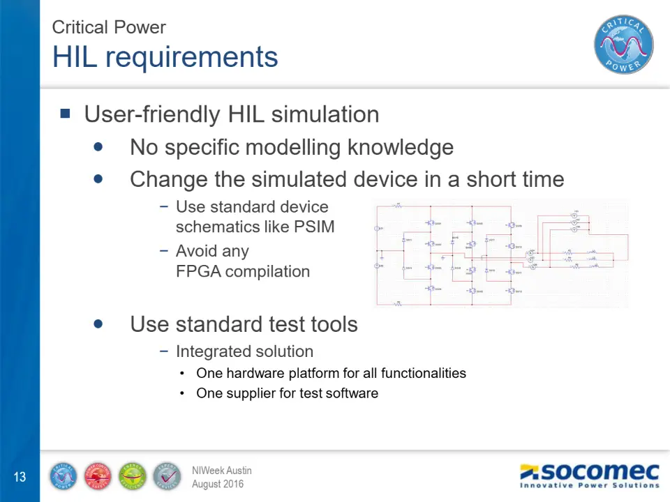
User-friendly HIL simulation
No specific modelling knowledge Change the simulated device in a short time
− Use standard device
schematics like PSIM
− Avoid any
FPGA compilation
Use standard test tools
− Integrated solution
- One hardware platform for all functionalities
- One supplier for test software
HIL requirements
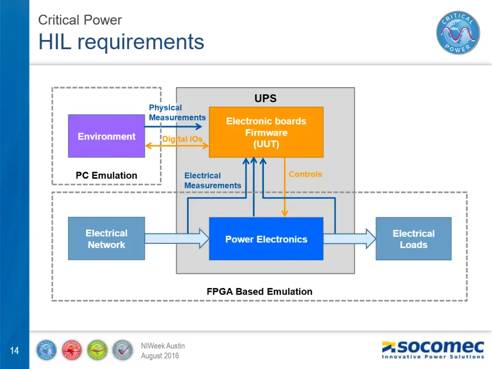
UPS
Physical Measurements
Electronic boards
Environment
Firmware
(UUT)
Digital IOs
PC Emulation
Electrical Measurements
Controls
Electrical Network
Electrical Loads
Power Electronics
FPGA Based Emulation
HIL requirements
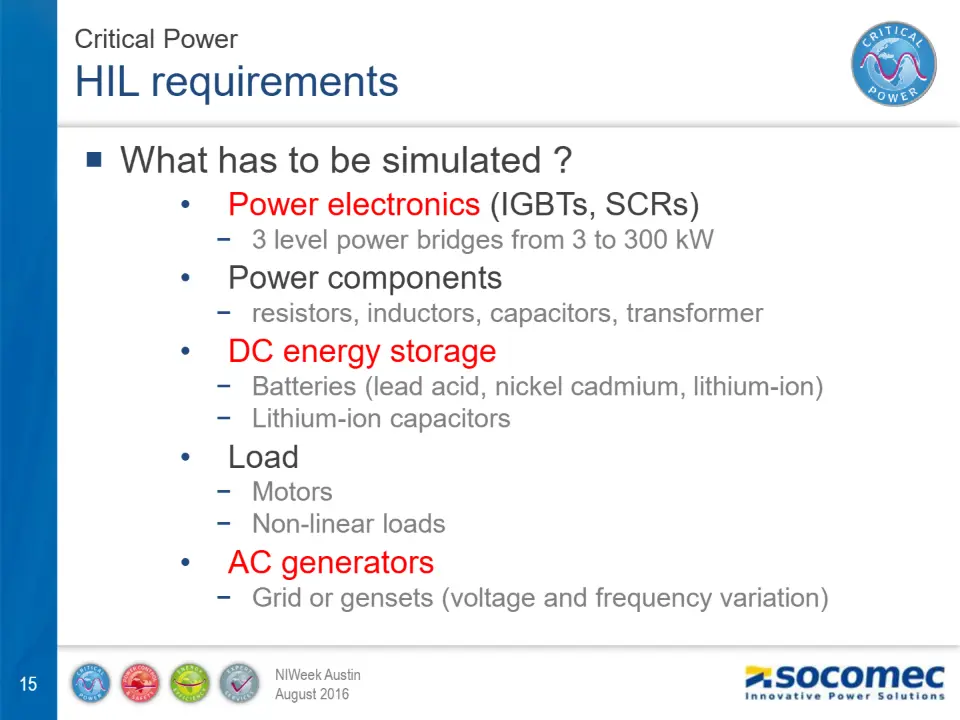
What has to be simulated ?
Power electronics (IGBTs, SCRs)
− 3 level power bridges from 3 to 300 kW
Power components
− resistors, inductors, capacitors, transformer
DC energy storage
− Batteries (lead acid, nickel cadmium, lithium-ion) − Lithium-ion capacitors
Load
− Motors − Non-linear loads
AC generators
− Grid or gensets (voltage and frequency variation)
eHS is a revolutionary floating-point solver for physical real-time simulation of an electric circuit on FPGA.
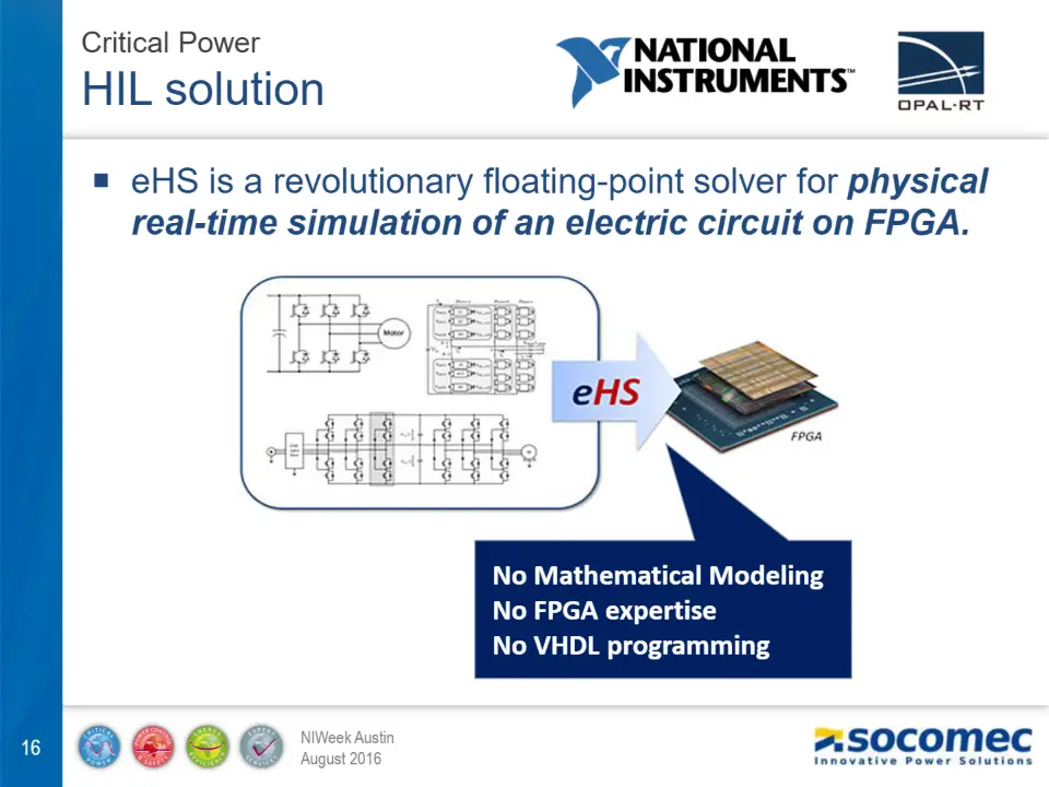
No Mathematical Modeling No FPGA expertise No VHDL programming
Opal-RT eHSx64 solver
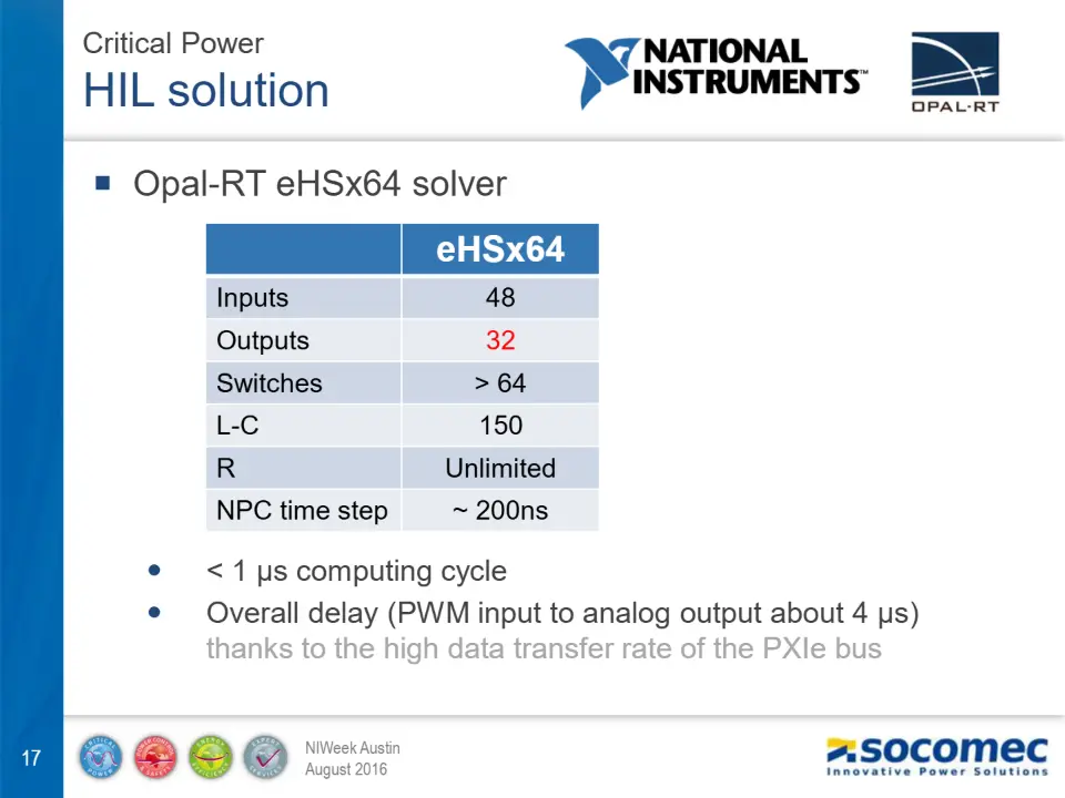
eHSx64
Inputs 48 Outputs 32 Switches > 64 L-C 150 R Unlimited NPC time step ~ 200ns
< 1 μs computing cycle Overall delay (PWM input to analog output about 4 μs)
thanks to the high data transfer rate of the PXIe bus
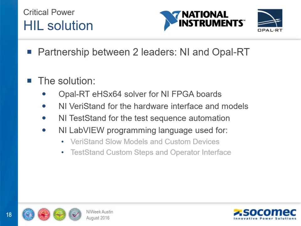
Partnership between 2 leaders: NI and Opal-RT
The solution:
Opal-RT eHSx64 solver for NI FPGA boards NI VeriStand for the hardware interface and models NI TestStand for the test sequence automation NI LabVIEW programming language used for:
- VeriStand Slow Models and Custom Devices
- TestStand Custom Steps and Operator Interface
System overview
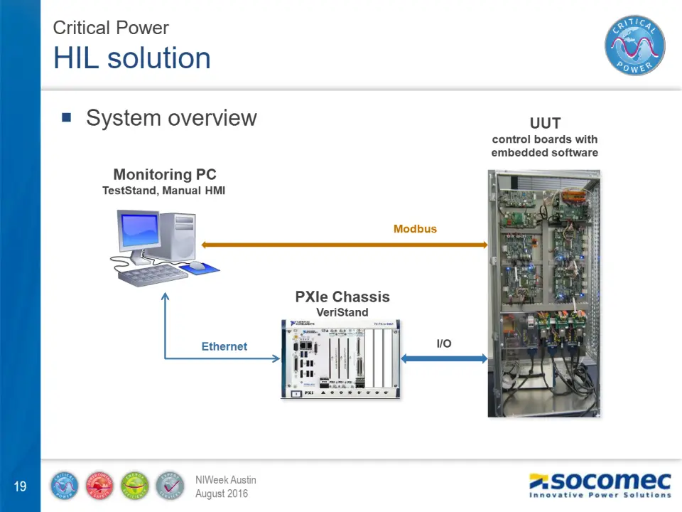
UUT
control boards with embedded software
Monitoring PC
TestStand, Manual HMI
Modbus
PXIe Chassis
VeriStand
Ethernet
I/O
Bay
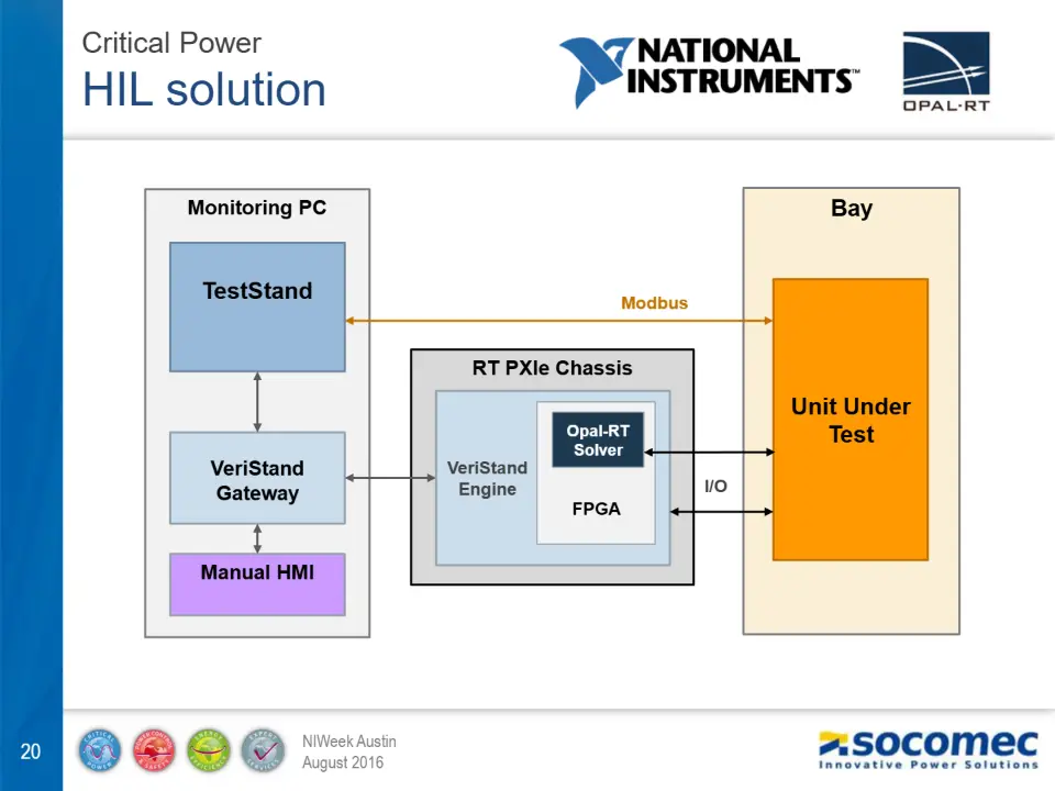
Monitoring PC
TestStand
Modbus
RT PXIe Chassis
Unit Under
Opal-RT Solver
Test
VeriStand Gateway
VeriStand Engine
I/O
FPGA
Manual HMI
Diapositive 21
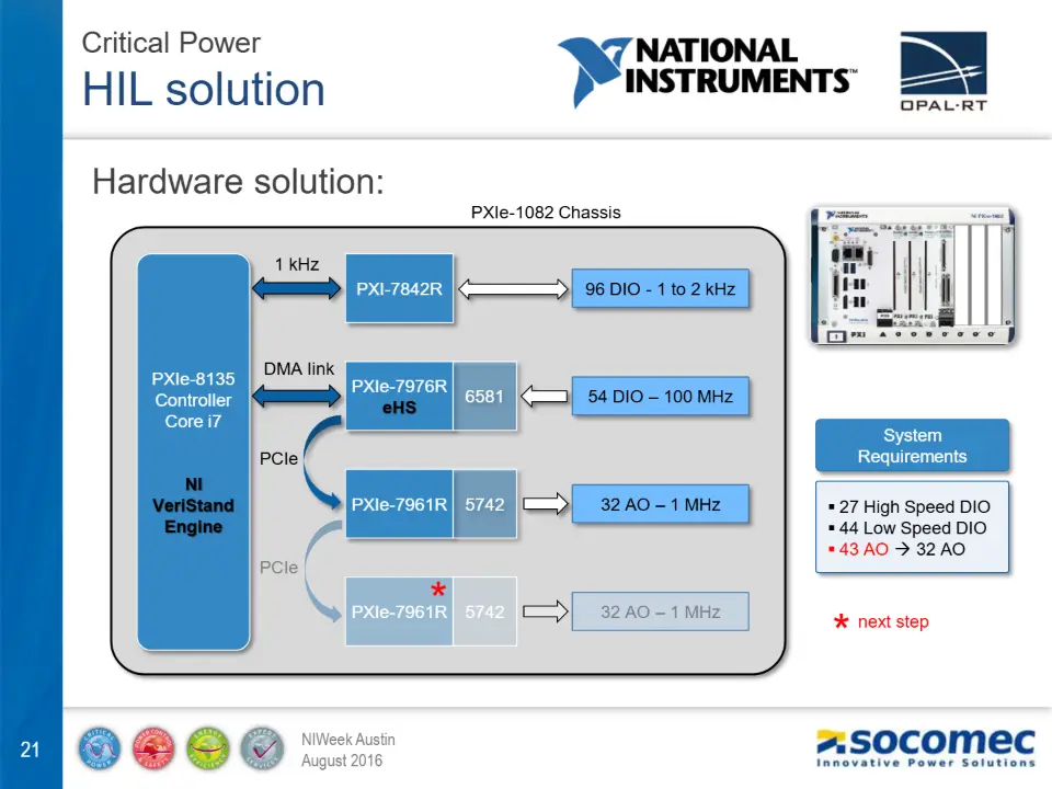
Hardware solution:
PXIe-1082 Chassis
1 kHz
PXI-7842R
96 DIO - 1 to 2 kHz
DMA link
PXIe-8135 Controller Core i7
PXIe-7976R
eHS
54 DIO – 100 MHz
System
PCIe
Requirements
NI
VeriStand Engine
PXIe-7961R
5742 27 High Speed DIO
32 AO – 1 MHz
- 44 Low Speed DIO
- 43 AO 32 AO
PCIe
PXIe-7961R
32 AO – 1 MHz
next step
HIL simulation results
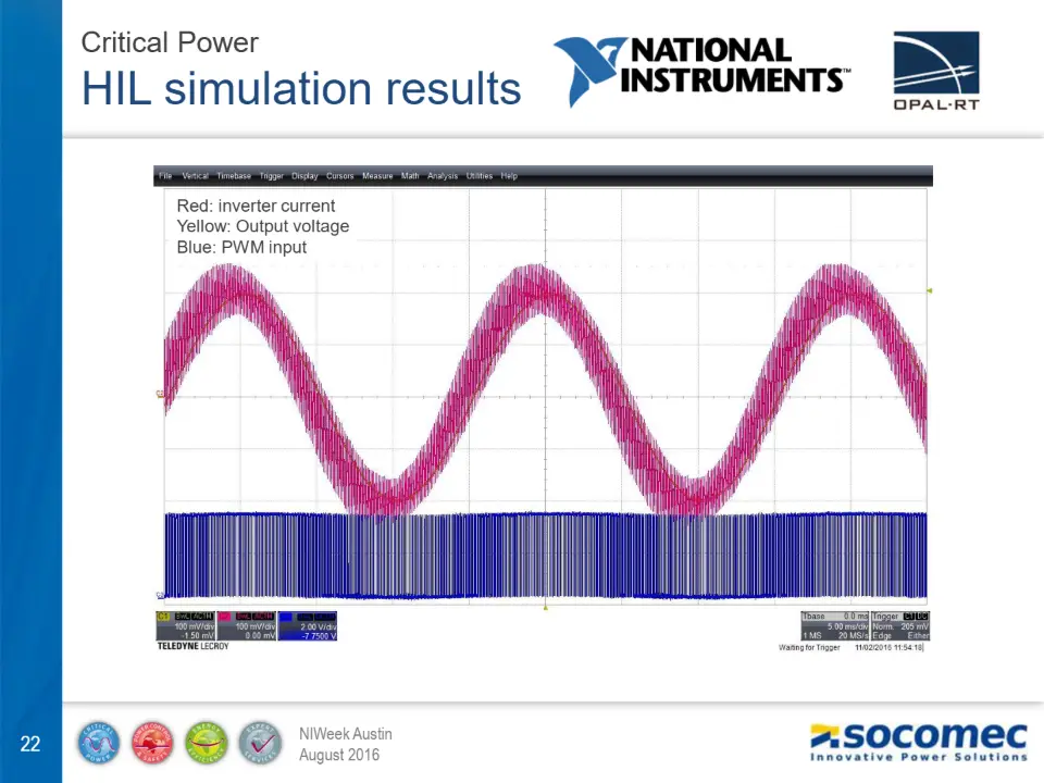
Red: inverter current Yellow: Output voltage Blue: PWM input
HIL simulation results
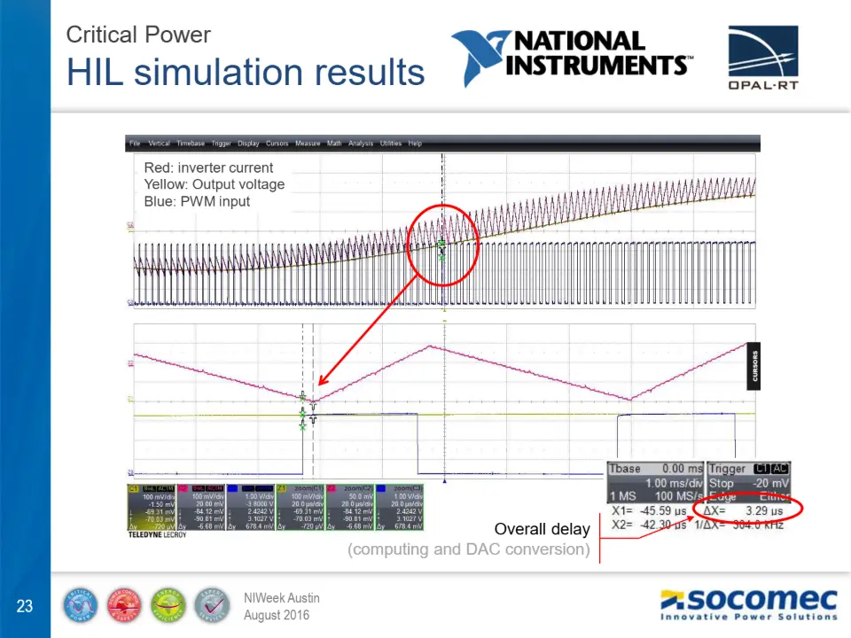
Red: inverter current Yellow: Output voltage Blue: PWM input
Overall delay
(computing and DAC conversion)
Collaboration with MESULOG, NI partner
Software architecture Manual HMI (Monkey Test) TestStand Step Types and Operator Interface Software development support and assistance
Manual HMI (Monkey test)
- User-friendly interface for operators
- Developed with LabVIEW and VeriStand API
- VeriStand Workspace not used by operators
- Will be integrated later into TS Operator Interface
Manual HMI (Monkey test)
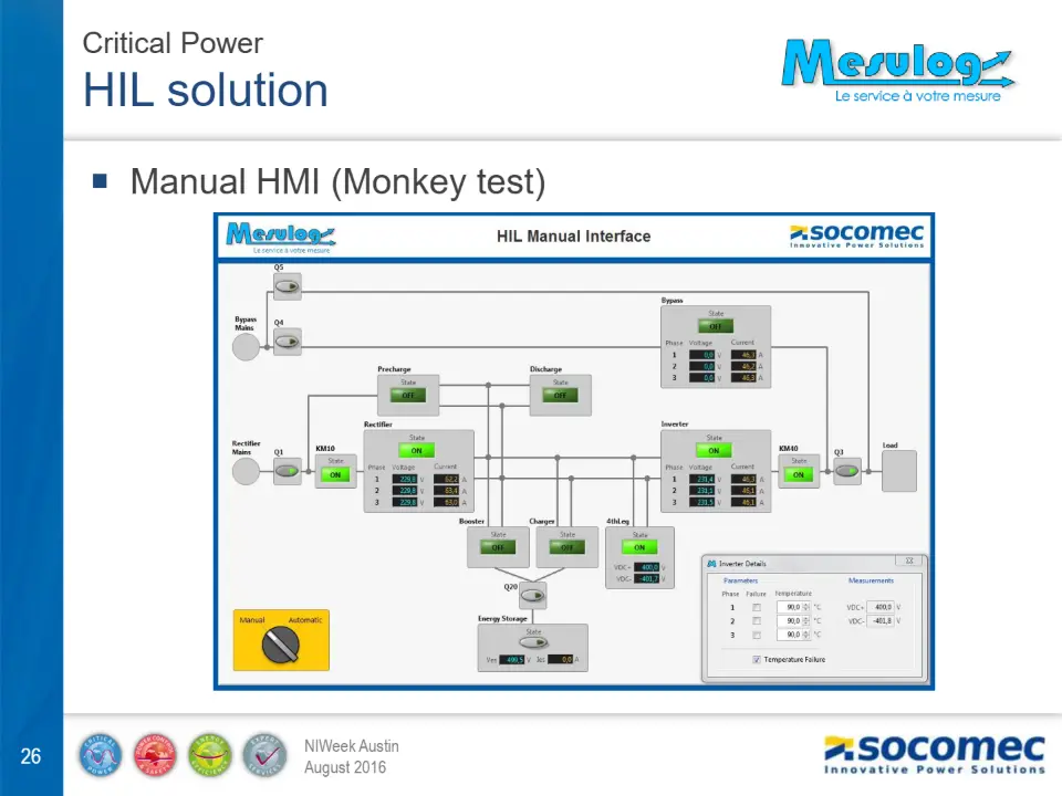
Manual HMI
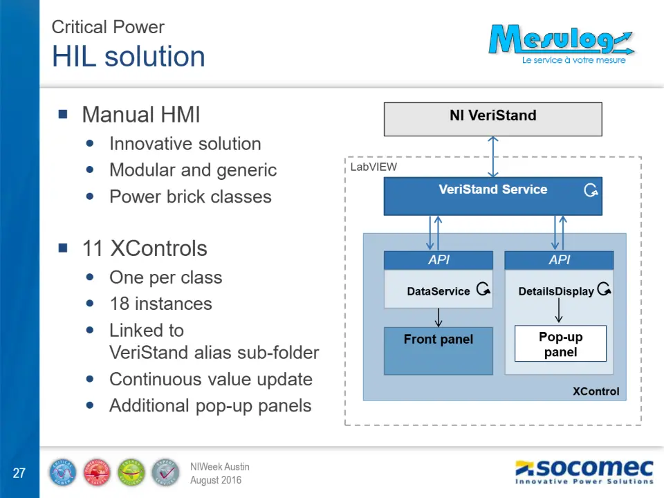
NI VeriStand
Innovative solution Modular and generic Power brick classes
LabVIEW
VeriStand Service
11 XControls
API API
One per class 18 instances Linked to
DataService DetailsDisplay .
Front panel Pop-up
VeriStand alias sub-folder
panel
Continuous value update Additional pop-up panels
XControl
TestStand Custom Step Types : PROTOCOL
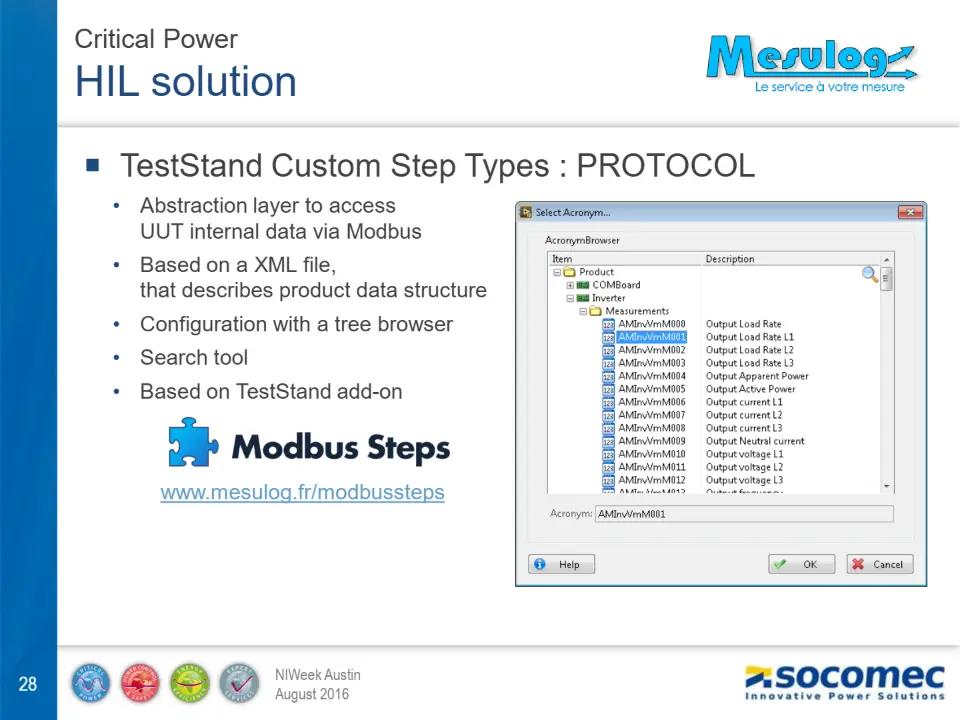
- Abstraction layer to access UUT internal data via Modbus
- Based on a XML file, that describes product data structure
- Configuration with a tree browser
- Search tool
- Based on TestStand add-on
www.mesulog.fr/modbussteps
TestStand Custom Step Types : VeriStand
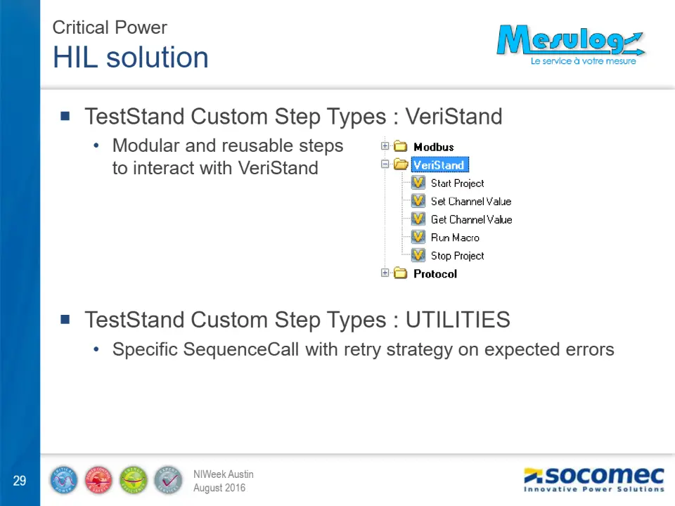
- Modular and reusable steps to interact with VeriStand
TestStand Custom Step Types : UTILITIES
- Specific SequenceCall with retry strategy on expected errors
HIL schedule
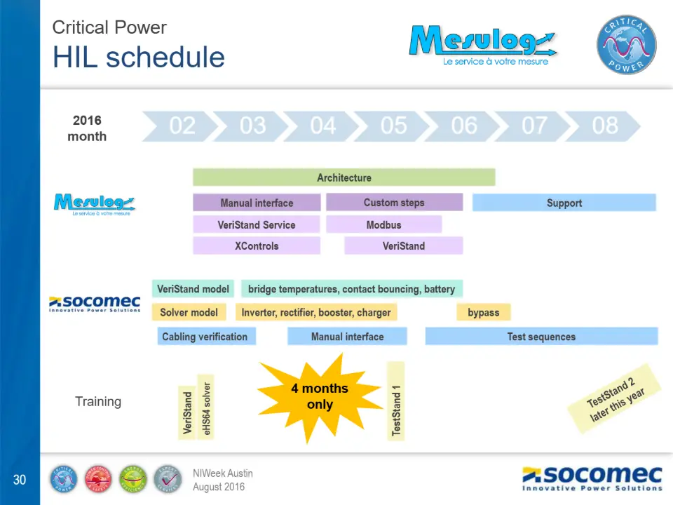
month
02 03 04 05 06 07 08
Architecture
Manual interface Custom steps Support
VeriStand Service
Modbus
XControls
VeriStand
VeriStand model
Solver model
Cabling verification
bridge temperatures, contact bouncing, battery
Inverter, rectifier, booster, charger
bypass
Manual interface
Test sequences
4 months
Training
only
VeriStand
eHS64 solver
TestStand 1
HIL results
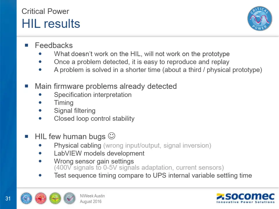
Feedbacks
What doesn’t work on the HIL, will not work on the prototype Once a problem detected, it is easy to reproduce and replay A problem is solved in a shorter time (about a third / physical prototype)
Main firmware problems already detected
Specification interpretation Timing Signal filtering Closed loop control stability
HIL few human bugs
Physical cabling (wrong input/output, signal inversion) LabVIEW models development Wrong sensor gain settings
Test sequence timing compare to UPS internal variable settling time
(400V signals to 0-5V signals adaptation, current sensors)
HIL evolutions
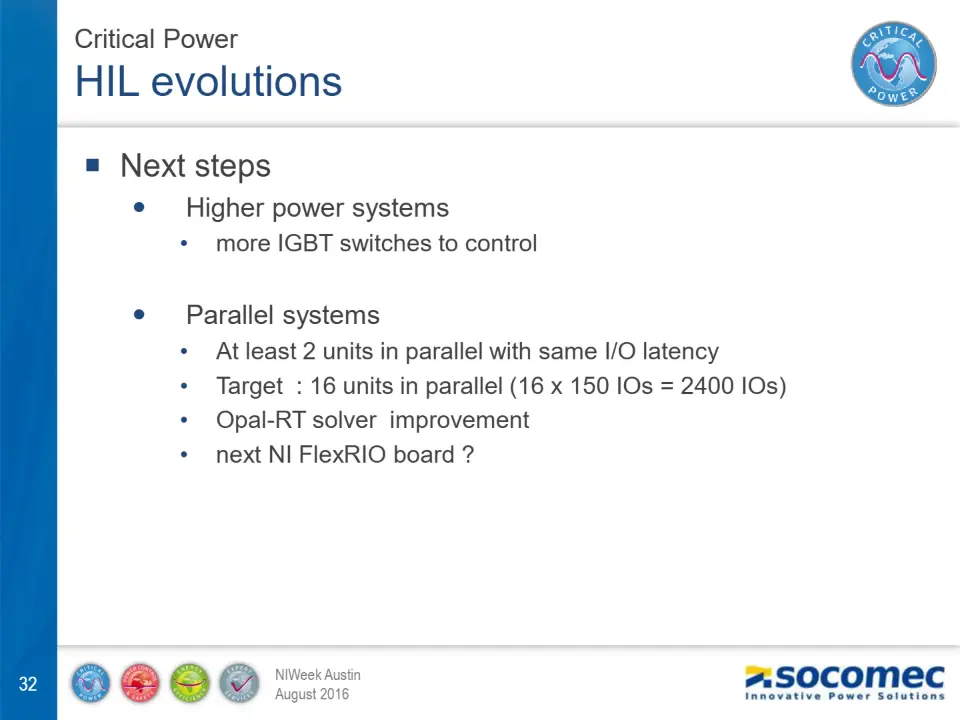
Next steps
Higher power systems
- more IGBT switches to control
Parallel systems
- At least 2 units in parallel with same I/O latency
- Target : 16 units in parallel (16 x 150 IOs = 2400 IOs)
- Opal-RT solver improvement
- next NI FlexRIO board ?
My Conclusion
NI partner
SUCCESS
Diapositive 34

Contacts :
- SOCOMEC :
- NAT. INSTR. :
- MESULOG : web@mesulog.fr


